How to make nature shaders with Shader Graph in 2022 LTS


In this blog, we explore how to create two distinct nature shaders using Universal Render Pipeline (URP) in 2022 LTS. We also take a closer look at a stylized water shader and a semi-realistic sand shader. The assets will be released with the new URP 3D sample scenes in the Unity Hub later this year.
The visual effects appear complex at first glance, but we’ll dive into the design-based thinking process behind these features and cover step-by-step breakdowns of the techniques that bring them to life. Let’s explore the intricacies of shader development and create stunning nature shaders.
Water shader
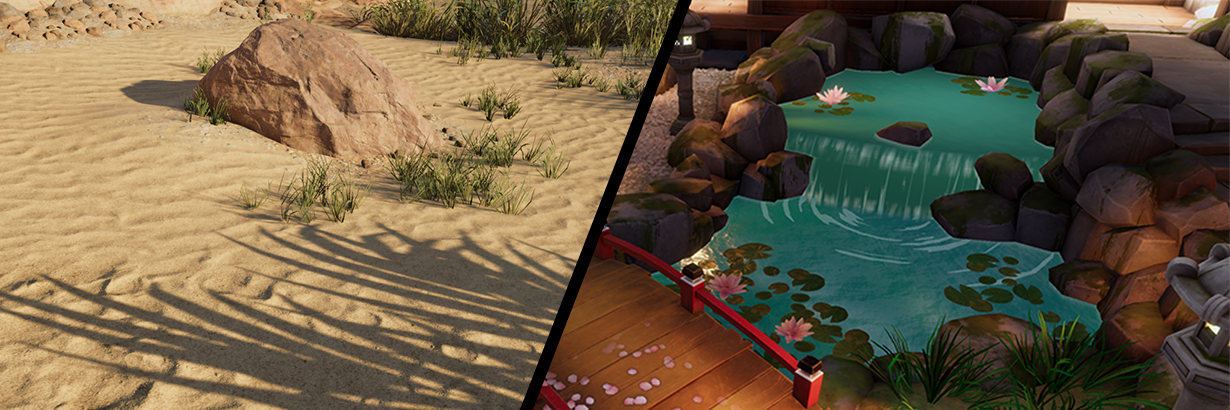
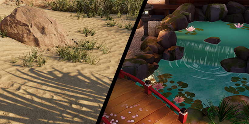
The goal, as depicted in the video above, is to create a stylized stream that runs in the middle of a Japanese-style garden scene. Based on the rest of the environment, the atmosphere is quiet and zen-like, and the art style is more animated than photorealistic.
From the terrain embedded in the scene, the water is a combination of two parts: a waterfall, and a stream running under the bridge. The water scenes from Studio Ghibli are very inspiring, and frequently have three distinct elements:
- Flow lines which help establish the flow of the water
- Edge highlights to show the water interacting with the surrounding terrain
- Foam effects to help sell cascades or waterfalls
The final water shader will use all of these elements. Now, let’s explore the details of how to achieve the look.
Waterfall: Foam and splashes
The waterfall has two distinct meshes – the primary waterfall mesh and a disc-shaped plane that generates ripples. Using a separate unlit shader for the ripples, you can tile a noise node and use it as the alpha value of the shader. This masks out the remaining areas, ensuring that the ripples appear where intended.
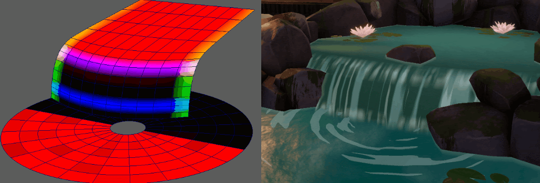
The most important part is to ensure that each area of the mesh can perform different behaviors. You can achieve this by pre-painting the meshes with vertex colors in the red (R), green (G), and blue (B) channels. The vertex colors are then used as masks to separate operations in certain areas.
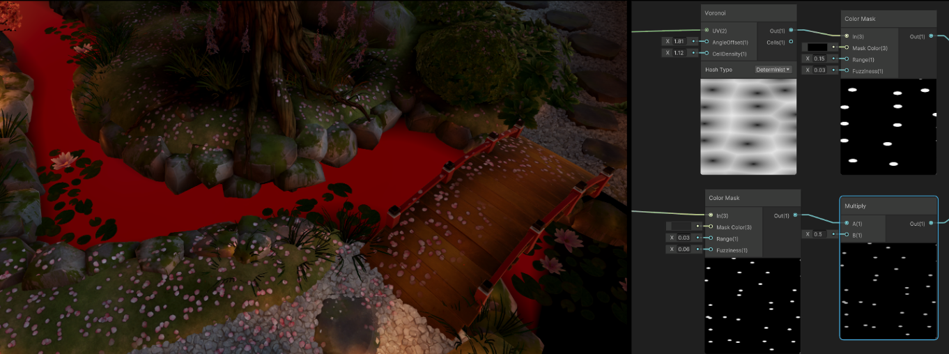
In Shader Graph, use the Vertex Color Node to access the pre-painted vertex color data. As seen on the right side of the image below, you can use the red channel in vertex color as your T value to interpolate (lerp) between the vertical and the horizontal part of the waterfall, achieving a smooth transition. To create a water cascading effect, combine two Voronoi Nodes, each with different tiling and offsets. This results in a dynamic visual of water falling.

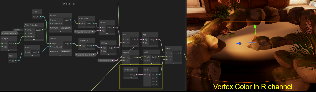
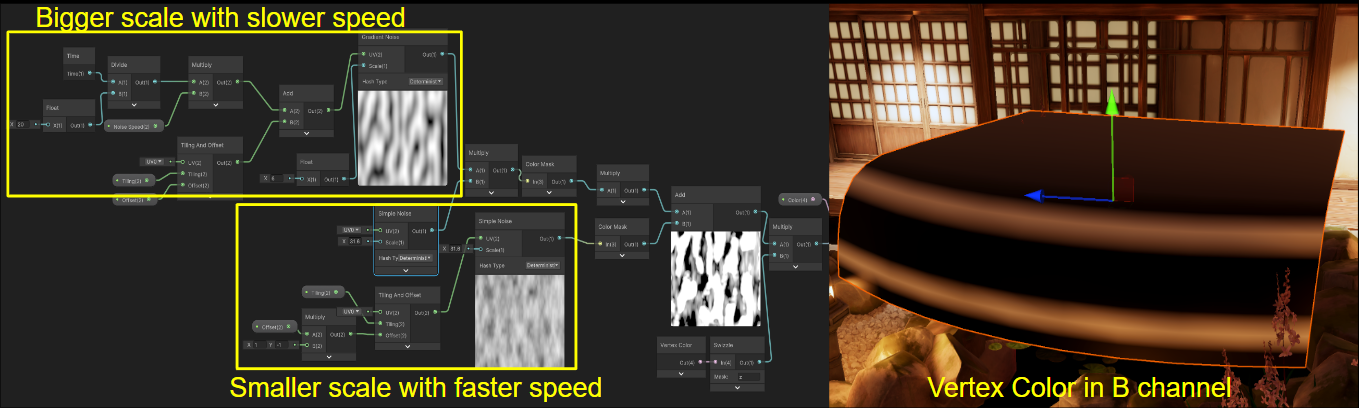
In real-life waterfalls, the areas where water cascades from the upper horizontal level and where it strikes the lower horizontal level often have thicker layers of foam and splashes. In the scene, you can pre-paint the vertex color in the blue channel to make sure the effects only show up in specific areas. Using vertex color masks enables you to combine up to four different effects into a single data piece. This approach is more efficient compared to creating separate grayscale mask textures for each effect.
To create the illusion of multiple layers of water falling from the edge, utilize noise nodes with different scales and speeds. By scrolling a noise node with a larger scale at a slower speed, alongside a smaller scale noise node at a faster pace, you achieve the desired effect. To maintain consistency with the horizontal part of the waterfall, reuse the data from the stream water. We will delve into further detail about the stream water shortly.

Stream: Reflections, edge foam, and water trails
Now that you’ve created a calming waterfall, let’s move on to the stream. There are several key features that animation-style water usually has. Unlike the turbulent shoreline foam found in the real world, a Ghibli-style stream typically has very thin foam near the shore. Additionally, the presence of water tails can bring a dynamic and lively impression to the water. Since the scene is set at night, a convincing reflection effect is also necessary. Let’s take a closer look at how you can achieve these effects in Shader Graph.
Reflections
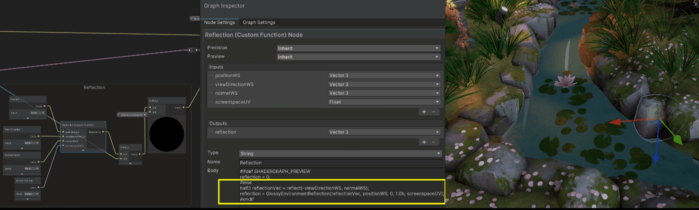
There are multiple ways to capture a reflection on the water’s surface. The most efficient option is a Custom Function Node that calls the GlossyEnvironmentReflection function built into URP. This function returns the reflection color, which is sampled from a box projection reflection probe in the scene. You just need to pass in the world space position, view direction, normal, and screen position required by the function.
If you need higher visual quality and more grounded reflections, URP’s planar reflections can be an excellent option. Planar reflection creates a mirror-like reflection of a flat surface, which is ideal for the water mesh, given its flat plane structure.
To achieve planar reflection, you need to set up a separate camera and render texture to store the reflection data. The basic concept is to place a reflection camera below the reflection plane (in this case, the stream in the scene) and update it based on the player camera’s position and orientation. The render texture will also be updated in real-time.
One advantage is that you can set the reflection camera’s near plane as the reflection plane itself. This eliminates the need to clip out objects that are located below the reflection plane, which simplifies the implementation process. In Shader Graph, you create a texture property, and in the script, you assign the render texture you previously created to it.
In order to link the render texture successfully, make sure that when setting the shader property, the property set matches the reference ID of the texture property you created in the Shader Graph. Make sure that the script calls the exact property ID when updating the render texture. Then, use the screen position as the UV to sample the texture. Now you have successfully achieved planar reflection in our shader.
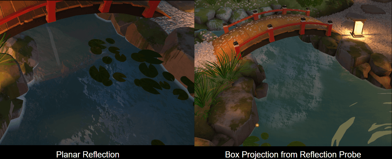
Implementing planar reflection involves several technical considerations and details. For a more in-depth understanding and an example of its implementation, feel free to take a look at this URP sample. One thing worth noting is that planar reflection is more computationally expensive compared to using reflection probes because it renders the objects twice.
Edge effect
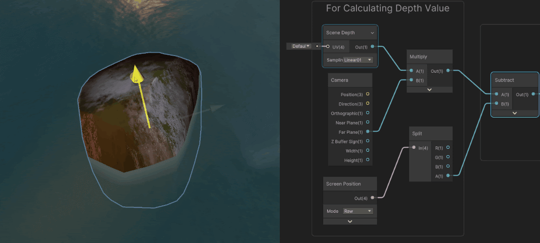
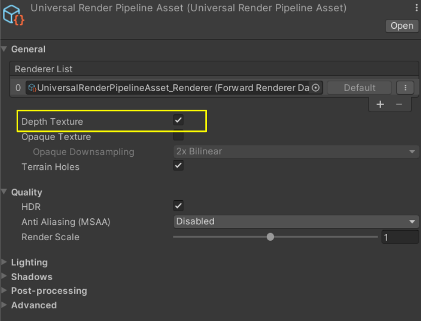
To achieve the edge foam effect, you need to calculate the depth differences. The Linear01 option in Scene Depth Node returns a linear depth value scaled from 0 to 1 for opaque objects. Multiplying this value with the Camera Far Plane Distance enables you to determine the distance between the camera and the opaque object – the rock, in this case. The z component of the Raw option in the Screen Position Node provides the eye-space depth. You can then calculate the depth difference between the transparent water surface and the opaque rock easily, and pass the depth value into the Emission output to create a foam-like effect.
In order to retrieve depth values from the scene, make sure to enable Depth Texture in the project settings. You can find the Depth Texture option in the General section of the render pipeline asset. The current render pipeline asset is accessible via Edit > Project Setting > Graphics > Render Pipeline Asset.

Stream lines
Creating the trails, which show the movement of the water along the stream, is straightforward. By tiling and offsetting two Voronoi Nodes and masking out the desired areas using vertex colors, you can create stylized water trails flowing along the water surface. Then, adjust the speed of the noise node to match with the previous falling water. You now have stylized water trails flowing through the water surface. This is very similar to the technique used to create the waterfall’s stream lines.

Sand shader
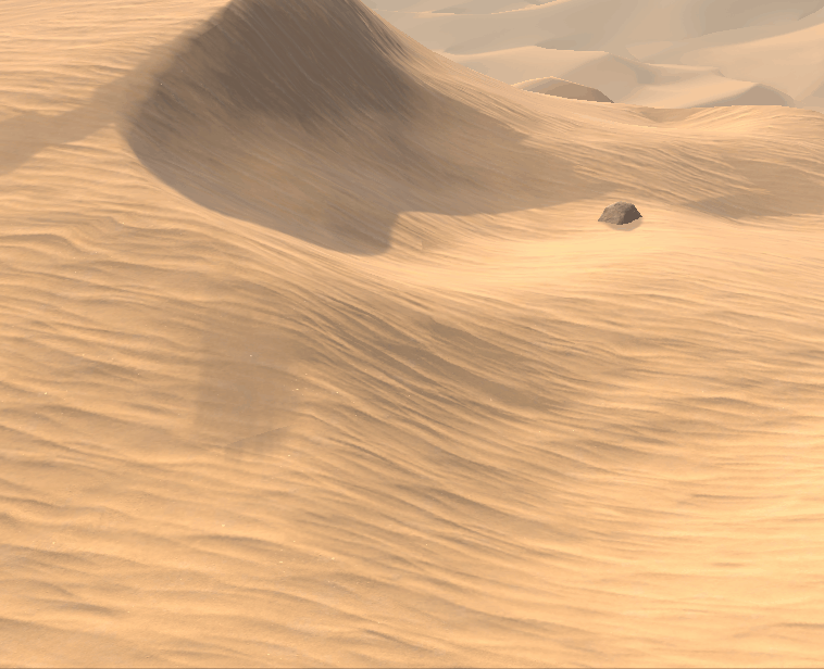
Now, let’s change gears and look at a less stylized, more realistic shader. The sand shader is in a realistic desert scene, which necessitates the terrain to closely resemble real-world sand visually.
Sand rendering is an interesting challenge. A plain PBR shader does not capture the look of desert sand under a strong sun. There are two main features to cover in the sand shader: the sand glitter, which is a subtle but noteworthy aspect, and the blowing dust, a dynamic feature that adds liveliness.
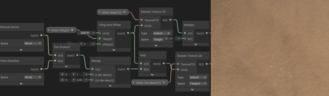
Since sand is composed of countless tiny grains, it sparkles when exposed to sunlight. How do you achieve that glitter effect? Similar to how you do specular reflection, first calculate the reflection vector using the surface normal. Taking inspiration from Journey, instead of calculating the dot product between the normal vector and the halfway vector, you calculate the dot product between the normal and the view direction instead. This adjustment ensures that the glitter pattern varies based on the viewing angles, enhancing the visual appeal of the shader.
You have two noise maps in the shader. One is used for sampling the sparkles, and the other is used to mask out the main noise texture for a more dynamic and captivating result. Use the previously calculated reflection vector to distort the UV used for sampling the noise mask.

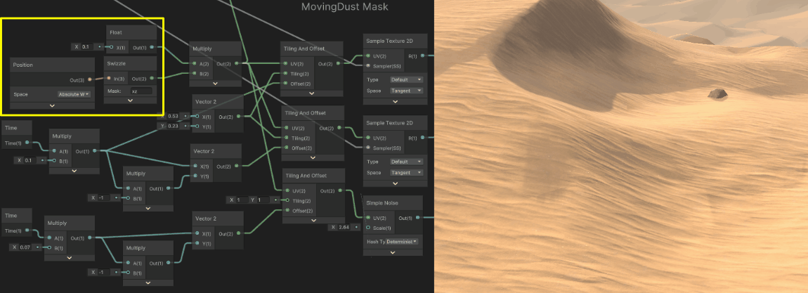
The blowing dust sand effect is a combination of two elements: moving sand trails and sand waves. The concept is fairly straightforward. You are tiling different normal maps to achieve the desired outcome. One key point for the sand trails is that you need a mask to mask out the normal map and make the effect look more dynamic. Instead of using the default UV, sample two noise maps with absolute world position.
One thing worth noting is that the World option in the Position Node changes based on the setting of different render pipelines, so select the Absolute World option to avoid any behavior changes when switching pipelines. Next, tile the two maps in a diagonal direction, which will create a ripple-like effect. Then scroll another noise map along the sand wave direction to add to the feeling of sand shifting away.
An important aspect is how to achieve normal blending in the shader. In a sand terrain, where the albedo map may not be as complex compared to other terrains, the normals play a significant role in the visual appearance. Blend multiple normal maps in the shader. Different from blending albedo maps, the normal maps store directions, and different blending methods can yield very different results.
Let’s take the Normal Blend Node in Shader Graph as an example. When blending normal maps A and B, the default option in the Normal Blend node adds the x and y channels of the two maps together, while multiplying the z channels to obtain the third element of the blended normal. The reoriented option, as the name suggests, involves a more intricate process. It rotates the normals in map B to align with the direction of map A. This approach retains the most data from both maps, but it is also the most computationally expensive option.

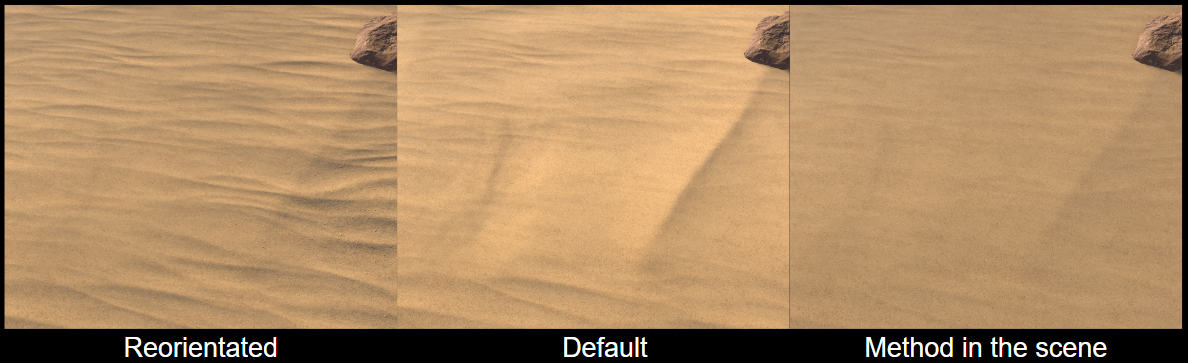
In our shader, we have opted for a simple blending method for the normals. The main reason for blending the normals is to create a vivid sensation of sand blowing or moving across the desert surface. Accuracy is not the top priority. Additionally, the shader is applied to a relatively large terrain mesh, so minimizing computational costs is important.
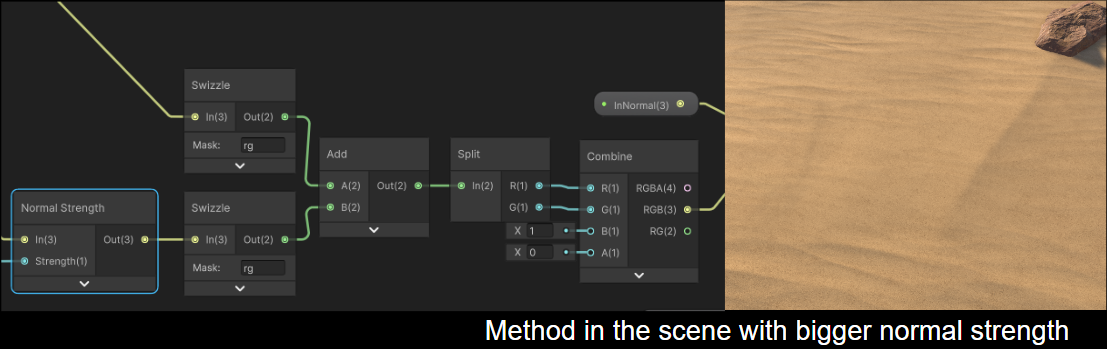
Considering these factors, here is a straightforward approach: Add the red and green channels of the normal maps together, and, for the blue channel, pass in a value of 1. Then, scale up the normal strength a little bit, and the result looks great.

In addition to the discussed features, there are other controls implemented in the shader. One of these is a general fading control, which determines where the effects appear on the terrain based on the camera distance. This allows for a gradual transition and fading of the effects as the camera moves further away.
You can also adjust the smoothness value in the distance, enabling better blending of the sand dunes and the background terrain. As the viewer zooms in, a detailed graininess normal map replaces the terrain normals. This substitution provides a more realistic desert experience, adding finer details and textures to the sand surface.
Now that you’ve gone through all the features in each of these two shaders, don’t hesitate to create your own versions. If you are passionate about creating shaders with Shader Graph, join our forum or find us on Discord. Be sure to watch for future technical breakdowns from Unity developers as part of the ongoing Tech from the Trenches series.
Is this article helpful for you?
Thank you for your feedback!
- Unity Labs
- Copyright © 2024 Unity Technologies